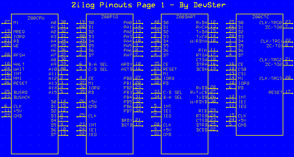
Data Bus:
D0-D7: System Data Bus. Transfers all data and commands between the Z-80 CPU and the Z-80 CTC. All are bidirectional, 3 state inputs/outputs.
Control Signals
CE: Chep Enable. When enabled the CTC accepts control words, interrupt vectors, or tie constant data words from the data bus during an I/O write cycle. Transmits the contents of the down-counter to the CPU during an I/O read cycle. In most applications this signal is decoded from the eight least significant bits of the address bus for any of the four I/O port addresses that are mapped to the four counter-timer channels. Input - active low.
RD: Read Cycle Status. Used in conjunction with IORQ and CE to transfer data and channel control words between the Z-80 CPU and Z-80 CTC. Input - active low.
CS0, CS1: Channel Select. Two-bit binary address codes selects one of the four CTC channels for an I/O write or read. Input - active high.
M1: Machine Cycle One. When M1 and IORQ are active, the Z-80 CPU is acknowledging an interrupt. The Z-80 CTC then places an interrupt vector on the data bus if it has the highest priority, and if a channel has requested an interrupt (INT). Input - active low, directly connected to the CPU.
IORQ: Input/Output Request. Used with CE and RD to transfer data and channel control words between the Z-80 CPU and the Z-80 CTC. During a write cycle, IORQ and CE are active and RD inactive. The Z-80 CTC does not recieve a specific write signal. It internally generates its own from the inverse of an active RD signal. In a read cylce, IORQ, CE and RD are active, the contents of the down-counter are read by the Z-80 CPU. If IORQ and M1 are both true, the CPU is acknowledging an interrupt request, and the highest priority interrupting channel places its interrupt vector on the Z-80 data bus. Input - active low.
RESET: Reset. Terminates all down-counts and disables all interrupts by resetting the interrupt bits in all control registers. The ZC/TO and the interrupt outputs go inactive, IEO reflects IEI., and D0-D7 go to the high-impedance state.
Interrupt Control
IEI: Interrupt Enable In. A high indicates that no other interrupting devices of higher priority in the daisy chain are being serviced by the Z-80 CPU. Input - active high.
IEO: Interrupt Enable Out. High only if IEI is high and the Z-80 CPU is not servicing an interrupt from any Z-80 CTC channel. IEO blocks lower priority devices from interrupting while a higher priority device is being serviced. Output - active high.
INT: Interrupt Request. Low when any Z-80 CTC channel that has been programmed to enable interrupts has a zero-count condition in its down-counter. Output - open drain, active low.
Channel Signals
CLK/TRG: External Clock/Timer Trigger. In counter mode, every active edge pulse on a pin decrements the down-counter. In timer mode, an active edge starts the timer. Input - active on active pulse, high/low, user-selectable.
ZC/TO: Zero Count/Timeout. Three ZC/TO pins correspond to a Z-80 CTC channel 2-0. Channel 3 has no ZC/TO pin. In both counter and timer modes, the output is an active high pulse when the down-counter decrements to zero. Output - active high.
Supply Signals
CLK: System Clock. Standard single-phrase Z-80 system clock. Input.